Crowdly
Add to Chrome
ECNG1012 : Engineering Science and Technology (Semester I- 2024/2025)
Looking for ECNG1012 : Engineering Science and Technology (Semester I- 2024/2025) test answers and solutions? Browse our comprehensive collection of verified answers for ECNG1012 : Engineering Science and Technology (Semester I- 2024/2025) at myelearning.sta.uwi.edu.
Get instant access to accurate answers and detailed explanations for your course questions. Our community-driven platform helps students succeed!
What steps must be taken to output a sine wave with a positive DC offset?i. Press button 1.ii. Press the square wave button in button group 3.iii. Press button 12. (Ensure that the button is down/depressed).iv. Rotate control knob 5 to the left.v. Rotate control knob 5 to the right.vi. Press the sine wave button in button group 3. 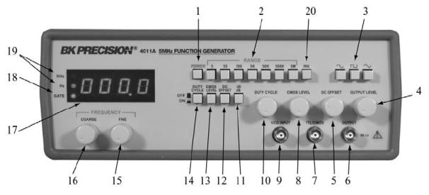
0%
0%
0%
0%
0%
View this question
<!-- /* Font Definitions */ @font-face {font-family:SimSun; panose-1:2 1 6 0 3 1 1 1 1 1; mso-font-alt:宋体; mso-font-charset:134; mso-generic-font-family:auto; mso-font-pitch:variable; mso-font-signature:3 680460288 22 0 262145 0;} @font-face {font-family:"\@SimSun"; panose-1:2 1 6 0 3 1 1 1 1 1; mso-font-charset:134; mso-generic-font-family:auto; mso-font-pitch:variable; mso-font-signature:3 680460288 22 0 262145 0;} /* Style Definitions */ p.MsoNormal, li.MsoNormal, div.MsoNormal {mso-style-parent:""; margin:0in; margin-bottom:.0001pt; mso-pagination:widow-orphan; font-size:12.0pt; font-family:"Times New Roman"; mso-fareast-font-family:SimSun; mso-fareast-language:ZH-CN;} @page Section1 {size:8.5in 11.0in; margin:1.0in 1.25in 1.0in 1.25in; mso-header-margin:.5in; mso-footer-margin:.5in; mso-paper-source:0;} div.Section1 {page:Section1;} /* List Definitions */ @list l0 {mso-list-id:553929561; mso-list-type:hybrid; mso-list-template-ids:-668544068 67698703 67698711 67698715 67698703 67698713 67698715 67698703 67698713 67698715;} @list l0:level1 {mso-level-tab-stop:.25in; mso-level-number-position:left; margin-left:.25in; text-indent:-.25in;} @list l0:level2 {mso-level-number-format:alpha-lower; mso-level-text:"%2\)"; mso-level-tab-stop:.75in; mso-level-number-position:left; margin-left:.75in; text-indent:-.25in;} ol {margin-bottom:0in;} ul {margin-bottom:0in;} -->
A resistor having a color code yellow, red, orange, and gold has resistor value between:
❌
❌
❌
✅
View this question
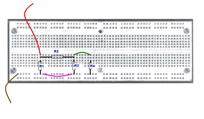
The yellow wire is electrically connected to the green wire through the breadboard.
100%
0%
View this question
A resistor was measured and its value was 3.6 kΩ . The color code of the resistor is orange, white, red and gold. Therefore, the measured value of the resistor is within its tolerance range.
0%
0%
View this question
With respect to the internal resistance of the voltmeter, the following statements are NOT true :
- The internal resistance of the voltmeter determines the accuracy of the voltage reading across the component.
- Voltmeters reduce the total resistance of the circuit, hence an internal resistance that is very low in comparison to the circuit, will give an accurate reading.
- False readings can occur due to the meter changing the circuit. If the voltmeter has a resistance that is too low in comparison to the component across which the voltage drop is to be measured, it will lower the net resistance of the circuit.
- Due to voltmeters being connected in parallel, they are not part of the circuit, hence they provide an accurate reading.
0%
0%
0%
0%
View this question
The following circuit was constructed in the lab on the breadboard shown below. Which of the wires shown is incorrect or unnecessary and should be removed?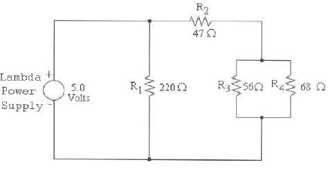
❌
✅
❌
❌
View this question
The yellow wire is electrically connected to the green wire through the breadboard.
100%
0%
View this question
A non-ideal voltmeter affects the circuit it is connected to by drawing a current through it. This is an example of meter loading.
100%
0%
View this question
A 22 kΩ resistor is displayed below.
0%
0%
View this question
The yellow wire is electrically connected to the green wire through the breadboard.
0%
100%
View this question